LED Driver Test Description

1.  LED Characteristic 

1.1 Fig. 2 shows Fig.1 LED’s equivalent circuit, there is a forward resister series a forward voltage Vd, the exponential V-I characteristic curve as Fig.3 When voltage across of LED larger than forward voltage Vd, then LED current Io is (Vo-Vd)/Rd. 


1.2 When LED driver is constant-current type, the voltage across of LED is Vd+(I*Rd)=Vo, Actually the Vd have a negative temperature coefficient (NTC -2mV//℃- -4mV/℃) with respect to voltage, e.g. the LED forward voltage Vd decreases as the LED gets warmer, causing the Vo voltage decreases as temperature goes up. 
 

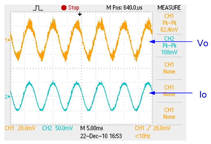
1.3 Right figure shows LED driver constant current output Io has a current ripple, The voltage across of LED also got a Io*Rd voltage ripple(Normally is a high frequency triangle waveform) 

1.4 Several LED cascading connection : Several LED cascading connection can get more output brightness, Vd and Rd also will increase as series. Fig. 4. Shows 3 LED series, Fig. 5. and Fig. 6. are the LED’s equivalent circuit, Fig. 7. shows exponential V-I characteristic curve.


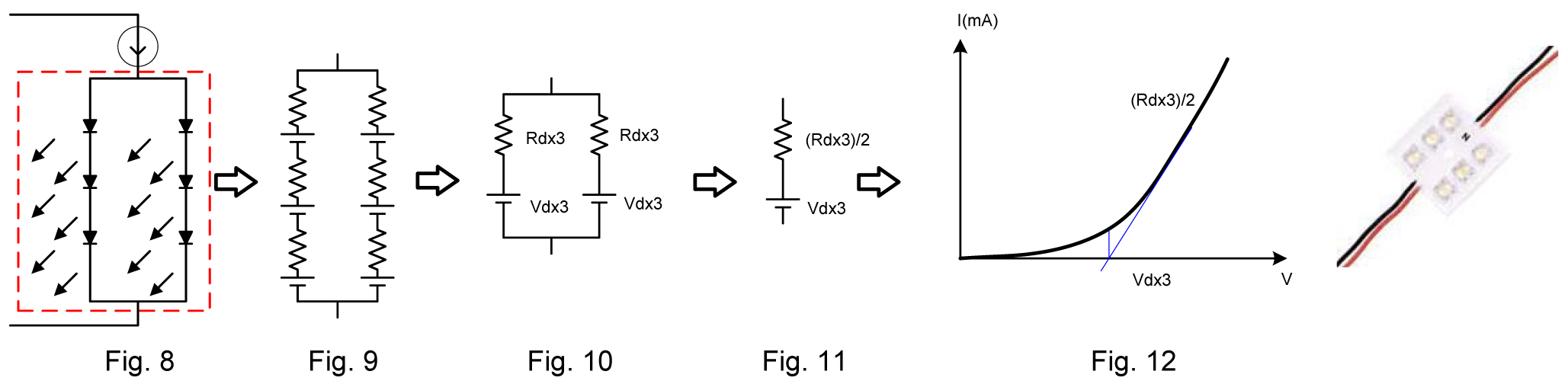
1.5 In parallel connection stacks of LED : Several LED stacks in parallel connection is also can get more output brightness, Vd also will increase as series, Rd is according to the cascade and parallel. Fig. 8. is 2 stacks LED to parallel, Fig. 9. to Fig.11. are the LED’s equivalent circuit, Fig. 12. shows exponential V-I characteristic curve. 


2. Real LED lamp load and electronic DC Load:
Below will explain what is the different in the test between real LED lamp load and electronic DC load, and what is the different of CC, CR LED mode of electronic DC load. 
 
2.1 Real LED lamp load (3W/3.85V/700mA series 10 LED )

2.2 Electronic DC load:

As the actual connection to the LED driver of the LED will be by brand, size, cascading, in parallel and then various different load conditions, if each test is required should be get the expensive cost of testing, the use of electronic load to simulate various combinations of LED to test can achieve fast and low cost. 


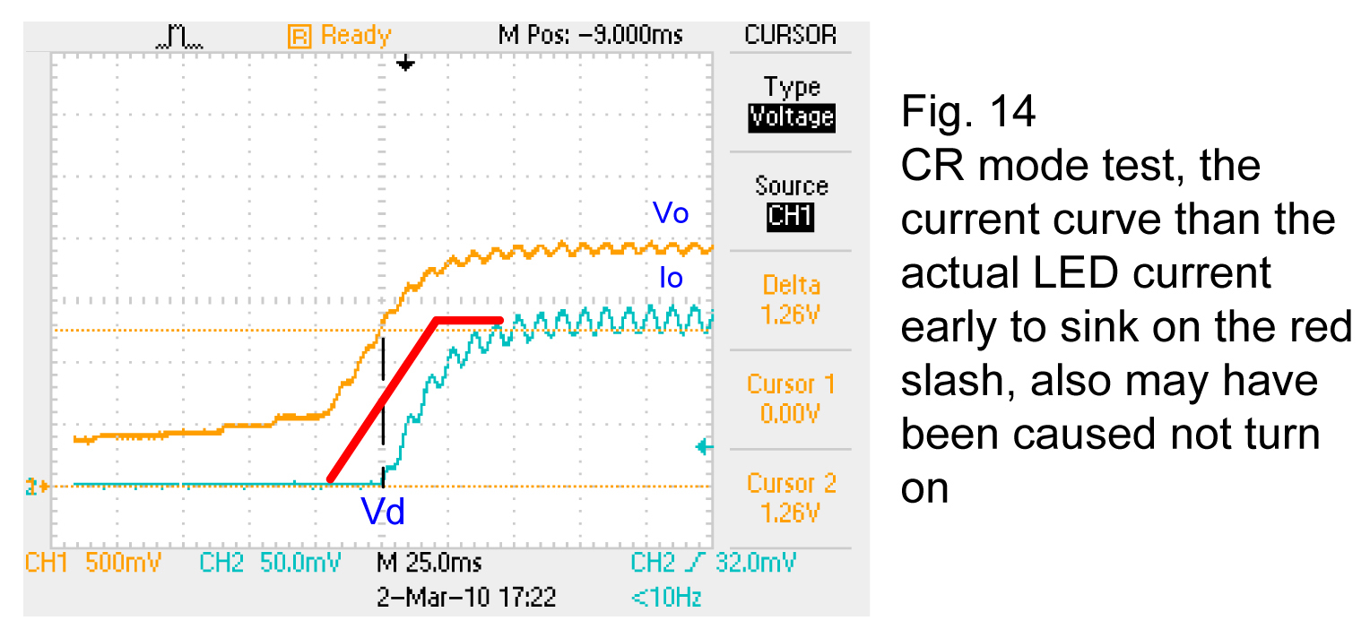
2.2.1 CR mode;setting R= Vo/Io, 38.5/0.7 = 55Ω


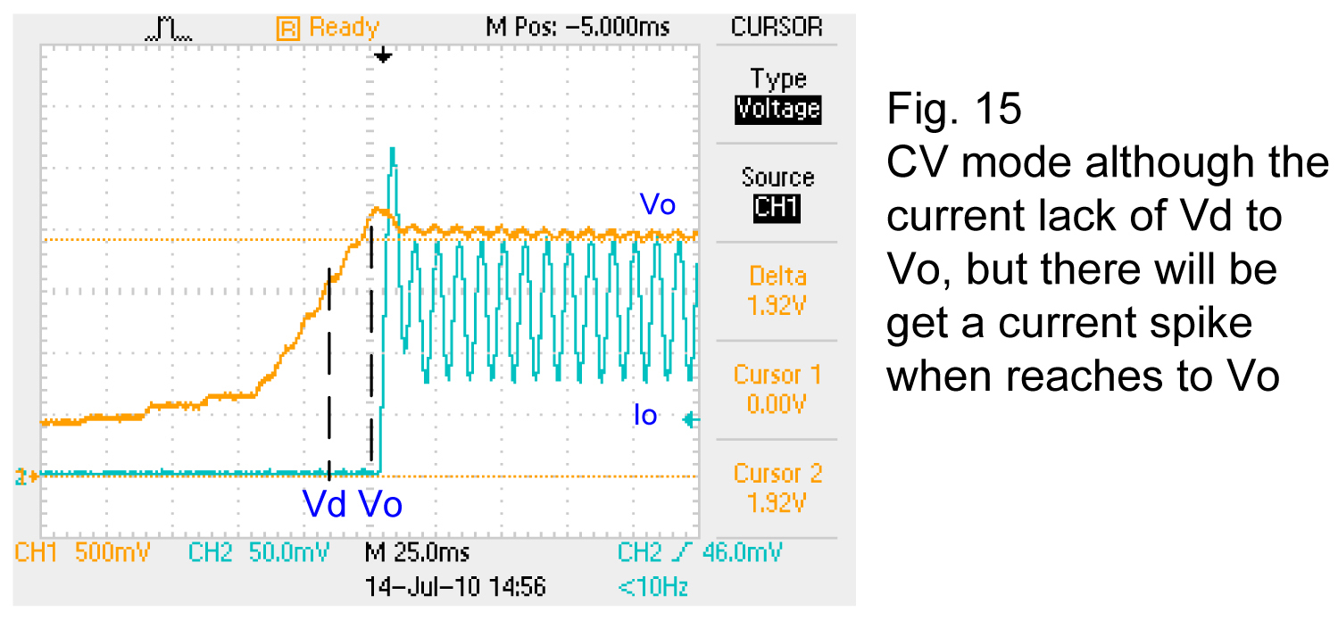
2.2.2 CV mode;setting CV mode, V=Vo

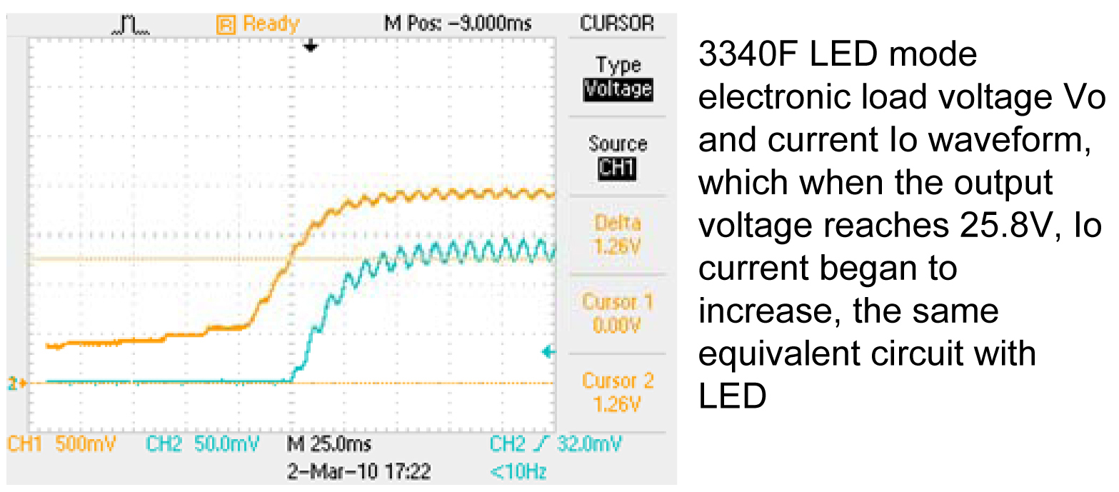
2.3 LED mode;LED mode electronic load is simulating LED’s equivalent circuit Fig. 2. , Combine the CR and CV mode, The 3340F series LED mode need to setting Vd and Rd, The output current will be as section 2.1 real LED lamp output current. 


3 How to setting Vd, Rd and Vo parameters for LED mode electronic load

a. If the LED lamp’s brand, parts no and specifications is available then follow the LED data to setting the parameters. 
 
b. If the LED lamp’s data information is not available, Normally, you can use the LED driver’s specification to setting the parameters, Vo is the LED driver’s output voltage specification, Vd can predict 70~90 percent of Vo (initial setting to 80%), Rd = (Vo-Vd)/Io, Io is the LED driver’s output current specification. 
 

3.1 Brand example I : LUXEON Rebel(Philips) specifications table 

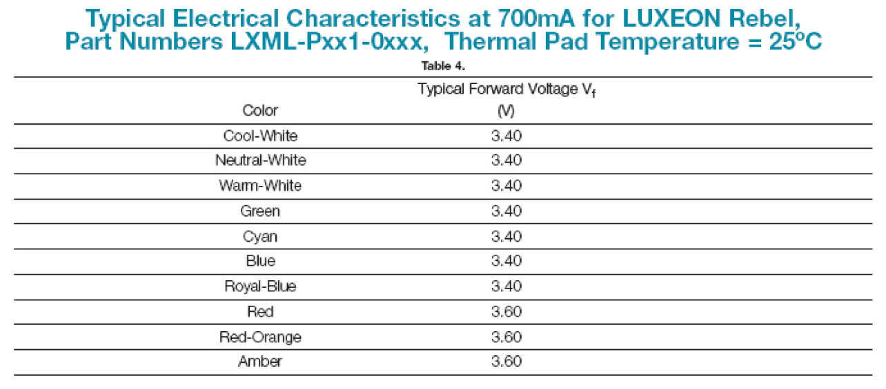
3.1.1 As specifications sheet you can find out Vo (it is equivalent to Vf, Typical Forward Voltage), Normally in the specification Vf (Forward Voltage) from LED manufacture is the LED’s output voltage Vo.

3.1.2 By the characteristic curve, as shown above the blue line drawing along the LED characteristic curve to find out forward bias voltage point Vd, Vd = 3.05V 

3.2 Brand example II : CREE, model XLamp-L 


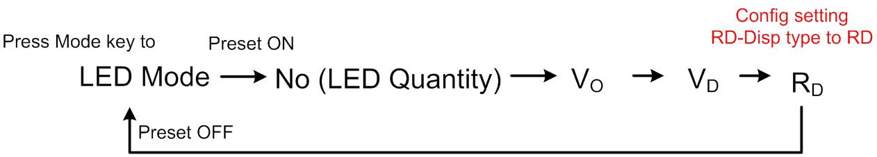
3.2.1 How to setting 3340F series LED mode parameter Vo, Vd, Rd and No 


3.3 Vo & Io setting and test result 
 
3.3.1 3340F series LED mode according with user’s setting Vo, Vd and Rd to simulating the LED characteristic curve as Fig. 3. LED characteristic curve. 
 
3.3.2 As Io is LED driver output, If LED driver actual output current not equal to specification output current that will be effect the output voltage Vo, EX. Io setting 150mA, actual LED driver output current 140mA, So the actual output voltage also will lower than the Vo specification, That can not use the ordinary electronic load’s CV or CC mode’s concept to check the Vo and Io, If use the actual output voltage test value to check the result that is not in accordance with Vo specification, in fact, this is the LED Driver’s output current has not correctly. 
 
4. LED driver’s short test 
 
4.1 Constant current output LED driver can not use the ordinary electronic load to do short test. 
 
4.2 3340F series LED mode load built-in a 12Vdc power supply for short relay control the external relay to do short test.


5. LED driver’s dimming test 
 
LED Driver dimming device can be TRIAC dimming or PWM dimming, the general E-Load response is too slow, can not be do LED Driver dimming test, 3340F Series LED mode Load increase the bandwidth (100KHz or more to) Improve the speed of response. 
 
5.1 TRIAC dimming is the use of TRIAC dimmer (currently on the market has been in use for many years incandescent dimmers, to use the TRIAC to adjust the voltage phase, to adjust the brightness of incandescent bulbs), LED Driver input connected to the dimmer, you can control the voltage phase changes of TRIAC dimmer, to adjust the LED Driver output current as well as the brightness of LED lights. 
 
5.2 PWM dimming mode dimming test it, must provide a control signal to the LED Driver dimming control input dimming for LED Driver test, 3340F Series LED mode Load provides a DIM Ctrl O / P voltage signal (adjustable 
voltage levels 0 ~ 10V, Duty Cycle 0.01 ~ 0.99 (1 ~ 99%), Frequency DC, 10Hz ~ 1KHz) as a module to achieve the function of the system. 


6. How to adjudge LED driver test is PASS or FAIL 
 
LED driver’s equivalent circuit as right figure, The LED driver’s tolerance as following 
 
6.1 LED driver’s current source Io. 
 
6.2 Different brand and specification have different Vd, Rd.


6.3 Different quantity LED cascading. EX. 3 LED cascade, 5 LED cascade will change with it. 
 
6.4 When temperature changes the Vd will decrease with increasing temperature -2 mV / ℃ ~ - 4mV / ℃, Rd also temperature coefficient, so the above test, the factors to be consider. 
 
Therefore, To test LED driver, set a different Rd, Vd have different Vo, (Vo = Io* Rd + Vd), not as a general constant voltage output Power Supply, with the CC test, the output voltage / current have general specifications (5%). Do not like the usual constant current output Charger, with the CV test, the output voltage / current with the general specifications), LED driver output Vo will be with Vd, Rd the set and have similar Corresponding changes. 

6.5 So test items in general have Vo, Io, short circuit voltage and PWM dimming function. 


Introduction of LED Driver Load

3340F Series LED Load Module
  • Application Note


  • Non-Linear V-I curve
  • Forward Bias (Vd) and Dynamic Resister (Rd)


Io=Vo-Vd/Rd

 
Key Features
 
  • Power Rating
3340F   300V / 2A / 150W
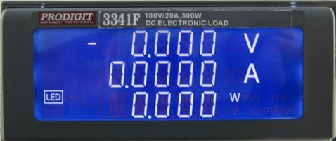
3341F   100V / 2 A / 300W
3342F   500V / 2A / 300W
33401F 500V / 2.4A / 120WX2
  • LED mode load for LED Power Driver test.
  • CC, CR, CV, CP, LED and Dynamic mode.
  • Simulate LED Forward Bias Voltage (Vd) and Resistance (Rd).
  • Fast Response for PWM dimming test.
  • Built-in dimming control signal for PWM dimming test.
  • Short circuit test by external relay (built-in short relay driver circuit). 
  • 5 digital V / A / W Meter.
  • Protections against V, I, W, and ℃.
  • Can be configured in 3302F〔single channel mainframe〕、 3305F〔two channels mainframe〕or 3300F〔four channels mainframe〕and the mainframe with 150 sets Store / Recall memory.
  • Optional Interface:GPIB、RS232、USB、LAN.
Independent dynamic loading parameter for each A/B channel : Up to 10KHz
  • Only need 0.8V/0.3V to draw rated current
  • Programmable slew rate, up to 1A/uS
  • Precision Voltage/Current/Power measurement 
  • OCP, OPP, Short circuit simulation
  • Full Protection : OV, OC, OP and OT protect 
  • Auto Sequence operating
  • GPIB, RS-232, USB, LAN interfaces
Why? LED mode Load
  • LED Driver test with different Load
Real LED Lamp
CR mode
CV mode
LED mode
  • LED Driver test with different Load
Real LED Lamp – Rd+Vd
CR mode
CV mode
LED mode


04.jpg

  • LED Driver test with different Load
Real LED Lamp
CR mode – Rd =Vo/Io ? LED driver may OVP shutdown
CV mode
LED mode
05.jpg


  • LED Driver test with different Load
Real LED Lamp
CR mode
CV mode – Vo=Vd? LED driver may OCP shutdown 
LED mode


07.jpg


  • LED Driver test with different Load
Real LED Lamp
CR mode
CV mode

LED mode – Vd+Rd


10.jpg


How to set LED Parameter : Vd, Rd
  • LED Data information
  • Real LED test result
  • Prodigit 3340D Led load
LED data information
  • LED Parameters : Vd (Forward voltage), Io 
11.jpg


LED Driver Specifications

How to get Vd and Rd

Check LED data information
1. LED data information, check I-V Curve of LED


Drawing a slop line

get Vd

How to get Rd ; (Vo– Vd) /Io, (3.38V-3.05V)/0.7 = 0.4714Ω


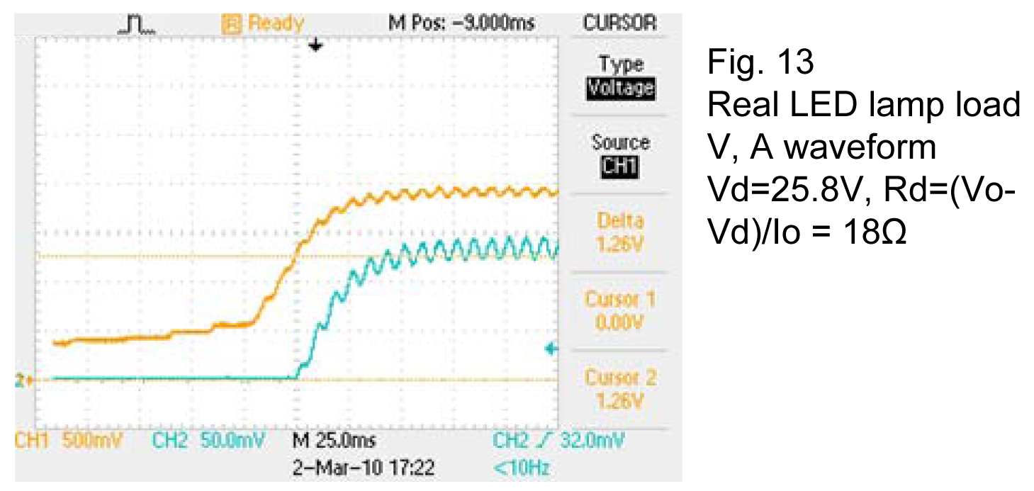
Check LED driver with real LED lamp

  • Real LED testing and record the voltage & current waveform
  • LED Driver Specification:30W / 0.7A
  • LED 3W(3.85V, 700mA) Series 10 PCs
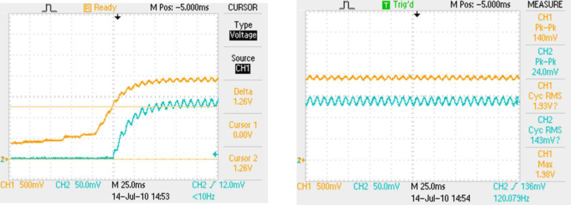
  • Test Result : Vo≒38.5V, Io≒700mA, Vp-p=2.4V, Ip-p=0.130mA(CH1 10V/DIV, CH2 250mA/DIV


Find out Vd from LED Driver turn on character curve


How to get Vd and Rd
Use 3340F series default setting
  • you can use the LED driver’s specification to setting the parameters, 
-Vo is the LED driver’s output voltage specification, 
-Vd can predict 70~90 percent of Vo (3340F Series default setting to 80%), 
-Rd = (Vo-Vd)/Io, 
-Io is the LED driver’s output current specification 
 
LED Load Parameter
 
Input LED quantity No. to calculated relative parameter automatically
EX. LED driver specifications Vout = 24V ~ 36V, IO = 700mA
If No. = 8, VO =3V, VD=2.4Vm RD=3-2.4/0.7 = 0.8571, test result VO =24V, IO=700mA
Change No.=12 than test result VO =36V, IO = 700mA

20.jpg

Input LED quantity No. to calculated relative parameter automatically
EX. LED driver specifications Vout = 24V ~ 36V, IO = 700mA
If No. = 8, VO =3V, VD=2.4Vm Io=0.700, test result VO =24V, IO=700mA
Change No.=12 than test result VO =36V, IO = 700mA

22.jpg


LED mode testing procedure

  • 3340F LED mode setting : No =1, Vo=38.5V ; Vd=25.8V ;Rd=18.007Ω
  • LED Driver Specification:30W / 0.7A
  • Test Result : Vo≒38.5V, Io≒700mA, Vp-p=2.8V, Ip-p=0.120mA(CH1 10V/DIV, CH2 250mA/DIV


Current Ripple

  • Iripple is produced by the LED driver's Vripple of LED's caused by the equivalent impedance Rd, Vripple / Rd = Iripple.
  • Adjust Rd to modify current ripple
  • Bandwidth set to Hi
-Press Config. key 6 times
-Hi : 140KHz(low current range)
-Lo : 20KHz (all range)


25.jpg


Measuring Average Function

27.jpg


Average Function : Press Config key 5 times
Average :1, 2, 4, 8, 16, 32 and 64
If the reading is unstable, please set the average to get the stable reading.


LED Lamp Dimming
  • DIM : Io (Level) control by analog voltage control


  • DIM : PWM Io by analog voltage control


  • PWM Freq. DC~1KHz, Duty 0.01~0.99(1~99%)


Short Test

  • Constant current output LED driver can not use the ordinary electronic load to do short test. Because the LED Load input impedance.
  • 3340F series LED mode load built-in a 12Vdc power supply for short relay control the external relay to do short test. 


Short Relay

  • Direct Plug in Short Fixture
  • No Relay Power Required
  • Two 250V relay cascade  to get 500V
  • Easy Relay Replacement


How to choose proper Model of 3340F series 
 

  • Linear Start up model or PWM start up mode 
-Backlight LED driver with PWM dimming (PWM start up model) : 3340F or 33401F(dual)
-Others can be any model (Linear start up by V/A/W rating)


3340F VS. Real LED Lamp
 
  • Linear ramp up type LED driver – SanSung STOOPA5804 58Vdc / 450mA LED Lamp 3W x 14


  • 3340F LOAD set 48.4V / 36V / 27.55 ohm

37.jpg

Applications


  • LED Driver power supply testing
  • Power Supply testing
-A/D Power supply
-DC/DC converter
-Battery Charger
  • Battery testing
  • Electronic & Electrical devices testing