

3271 AC & DC Electronic Load
- 3270 Series is suitable for the step, square and sine wave of the AC Power device test, especially for the uninterruptible power supply UPS, Inverter, fuses, circuit breakers, power regulator AVR, battery, AC / DC power supply / components ... and so on, absolutely is the best test solution in the market.
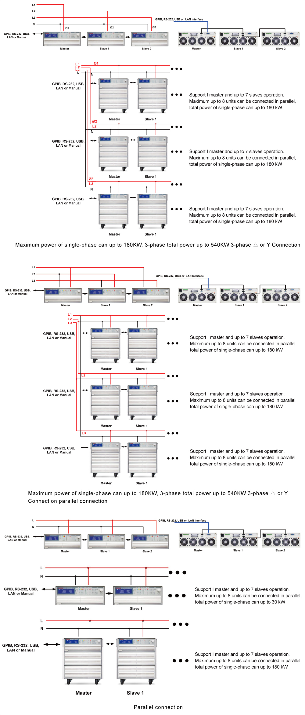
- Master / Slave has 2 operating modes
2. 3PH mode is for 3 phase application, three 3270 series can be connected for three phase Δ or Y connection, the setting current value (single-phase current value) will be sent to each Slave unit automatically, the user does not have to set each unit.
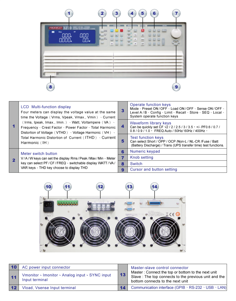
- 4 digit V / A/W Meter,display the Voltage(Vrms, Vpeak, Vmax., Vmin)、Current (Irms, Ipeak, Imax., Imin.)、Watt, Voltampere (VA)、Frequency、Crest Factor、Power Factor、Total Harmonic Distortion of Voltage(VTHD), Voltage Harmonic(VH)、Total Harmonic Distortion of Current(ITHD), Current Harmonic(IH)
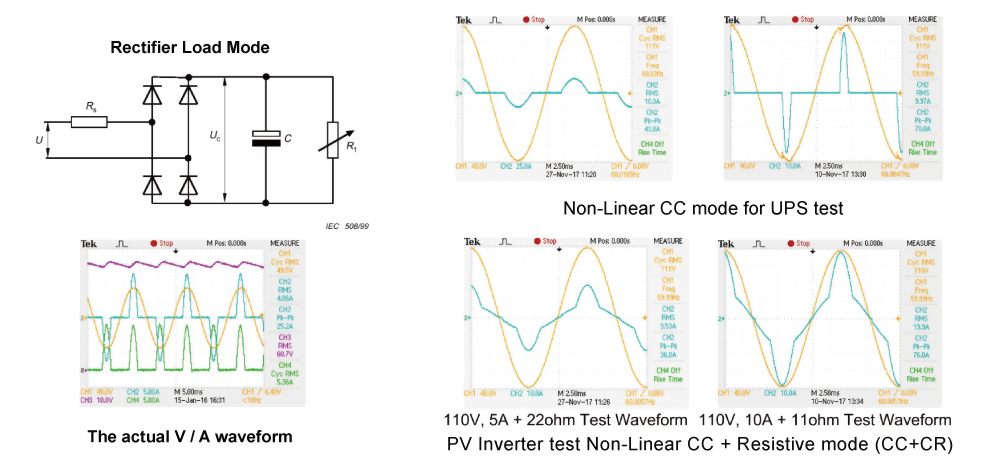
- CC, Linear CC, CR, CV, CP and AC Rectifier Load mode
-
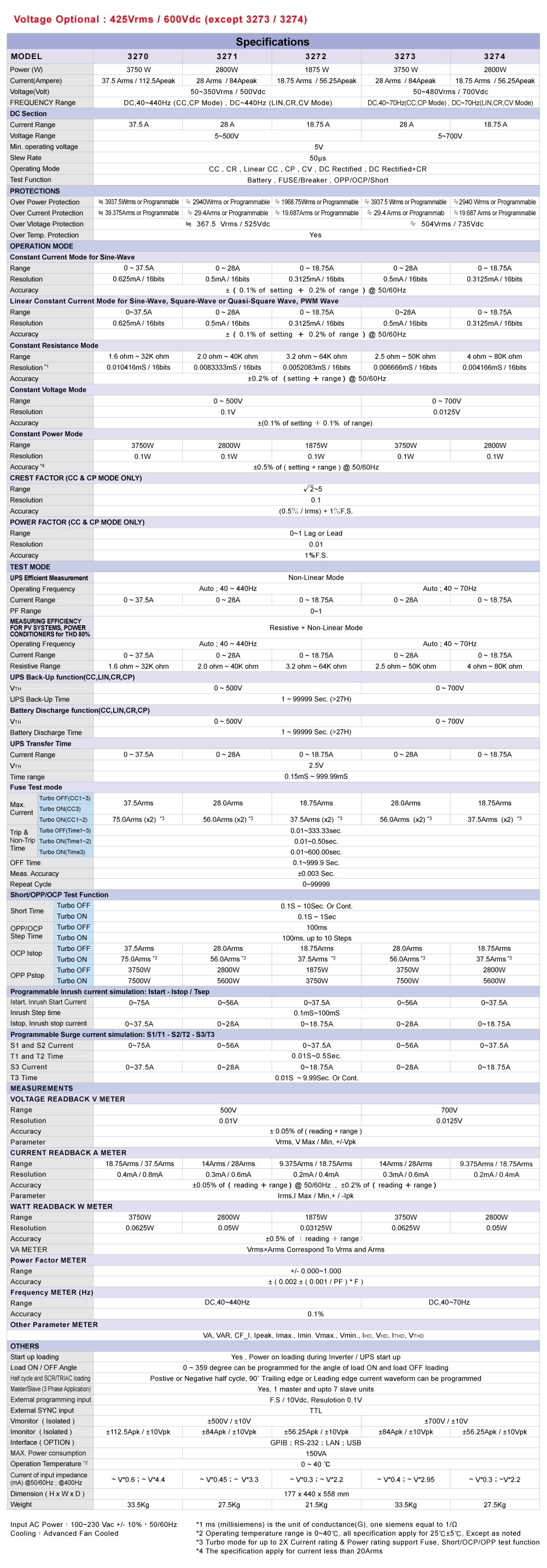
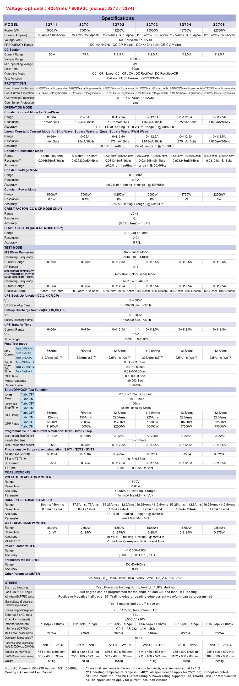
 Voltage Optional : 425Vrms / 600Vdc ( except 3273 / 3274)
- Crest factor range : 1.414~5.0
- Power factor(PF) range : 0~1 lead or(-1~0)lag
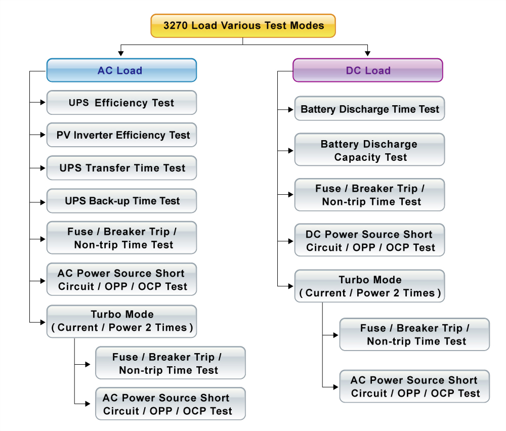
- Built-in function test modes include UPS Efficiency, PV Inverter Efficiency, UPS Back-up time, Battery Discharge time, UPS transfer time, Fuse/Breaker Trip/Non-Trip, Short circuit , OCP, OPP test modes
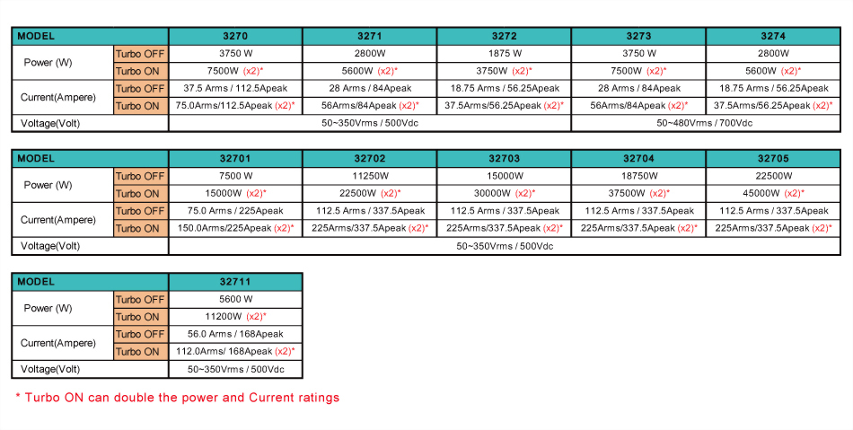
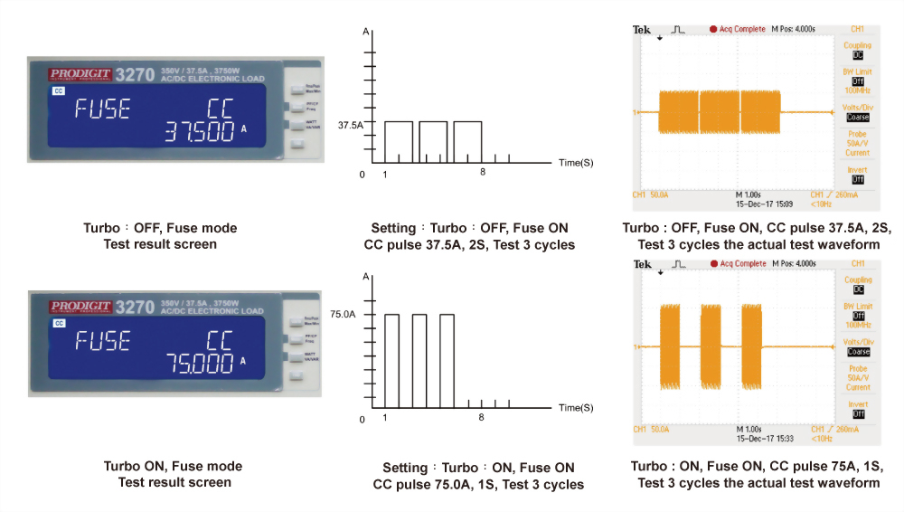
- Turbo mode is able to increase to 2 times the current and power of electronic load in a short period which is the most suitable for Fuse / Breaker test and short circuit, OCP, OPP test of AC power supply
- Time measurement can be applied to batteries, UPS, fuses and circuit breakers and other tests
- Eight units parallel up to 90KW and three-phase △ or Y load connection can be synchronized control by one master unit
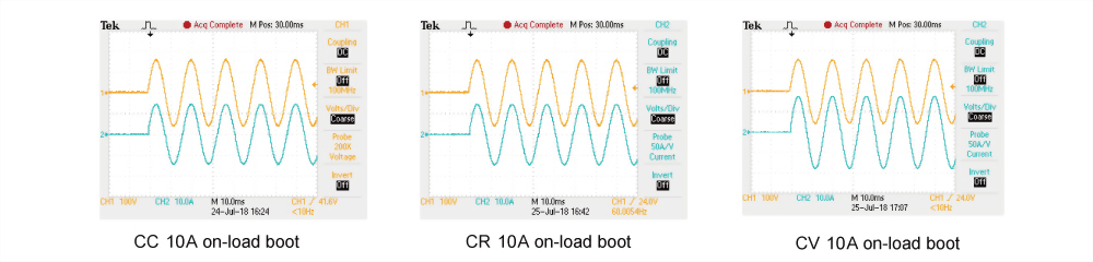
- Support on-load boot; at first set Load ON to support on-load boot, inverter or uninterruptible power supply is turned on directly with the set load current, used to verify whether the starter is stable when the Inverter is connected.
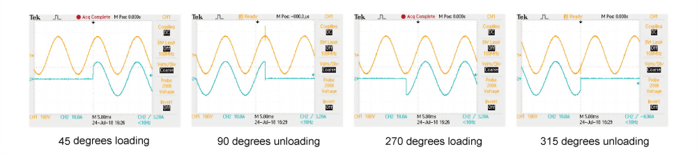
- Supports the loading and unloading angle control; the loading and unloading angle control, the full range of 0-359 degrees can be set to verify whether the Inverter output voltage transient response is stable when the actual electrical plugging and unplugging, and whether Overshoot/Undershoot is within the allowable range.
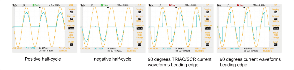
- Support positive half-cycle or negative half-cycle loading; used to verify whether the Inverter output voltage remains stable when the actual appliance has only positive half-cycle or negative half-cycle load current.
- Supports SCR/TRIAC current phase modulation waveforms, 90 degree Trailing edge and Leading Edge.
- Frequency Range : DC, 40~440Hz
- Voltage and current monitoring
- Can be controlled by external voltage for CC, Linear CC, CR, CV, CP operating modes
- Protection against V, I, W, and℃
- Optional interface:GPIB、RS232、USB、LAN
- The most complete measurement capabilities
3270 Series AC & DC electronic load built-in 16-bit A/D and DSP precision measurement circuit, provides accurate measurements, measurement items have Vrms, Arms, Watt, VA, CF, PF, THD, VTHD, ITHD, Ipeak, Amax, Amin, Vmax, and VminIn addition to these measurement functions, it also provides time measurement,products such as UPS, fuses and circuit breakers etc. trip or blow time and transfer time for Off-line UPS
Complete AC and DC load modes
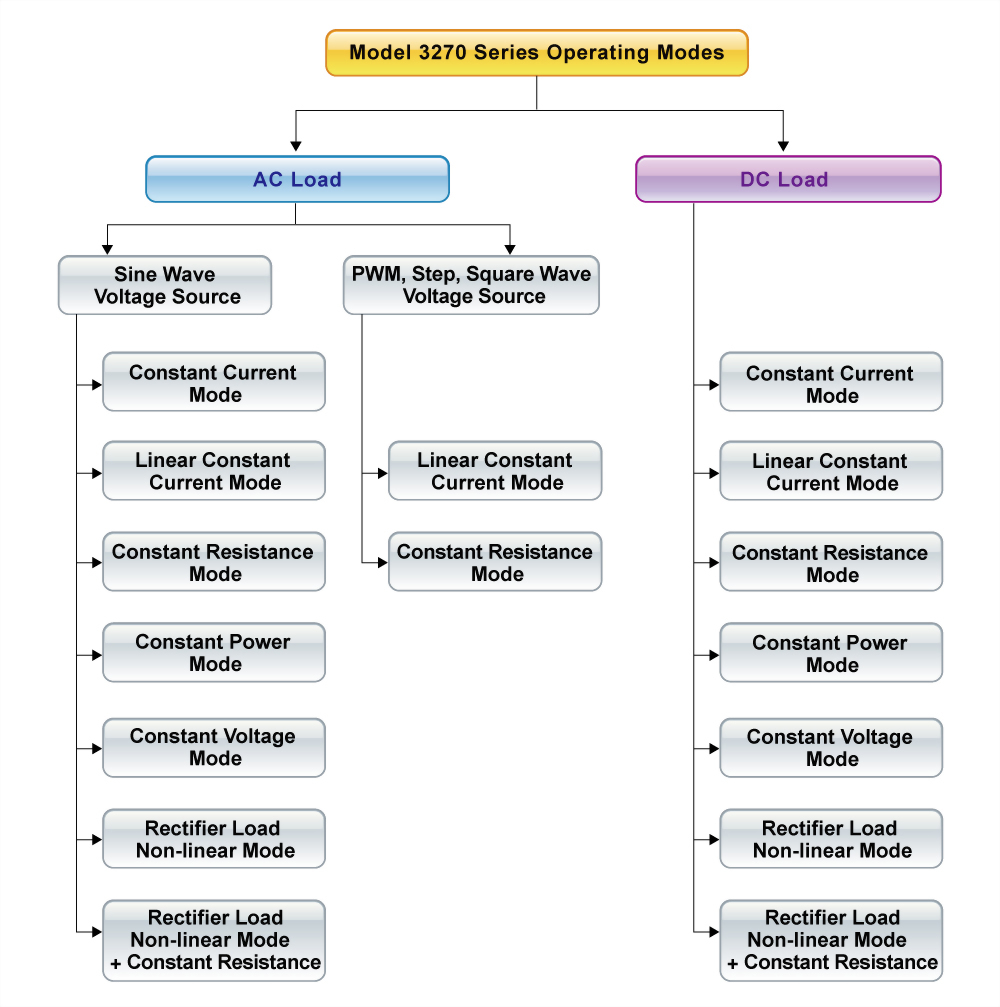
● AC Load Mode
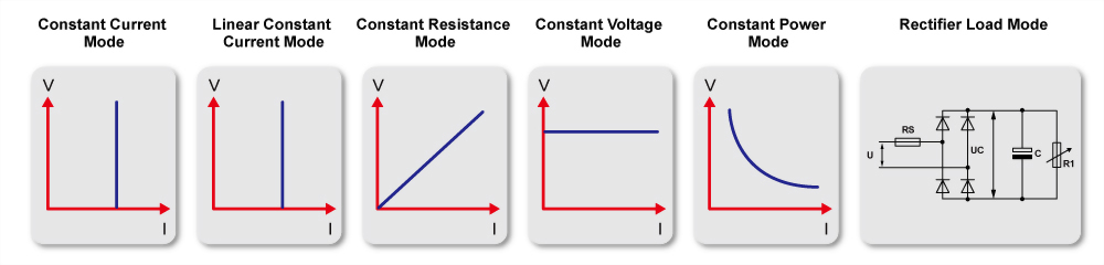
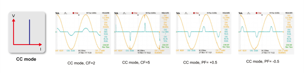
● CC Mode:In the constant current mode of AC Load, can be applied to sine wave voltage source, providing CF, PF test of linear load.
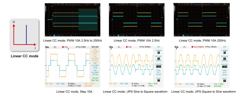
● Linear Constant Current Mode:Can be applied to sine wave and non-sine wave voltage source, as shown in the PWM inverter driver, step voltage source, and off-line UPS sine wave switch to square wave, square wave switch to sine wave.
● Supported on-load start-up:at first set Load ON to support on-load start-up, inverter or uninterruptible power supply is start-up directly with the set load current, used to verify whether the Inverter is stable when the load is connected during start-up.
● Supports the loading and unloading current angle control ; the loading and unloading current angle range of 0-359 degrees can be programmed to verify whether the Inverter output voltage transient response is stable during the actual electrical appliance is connected or turn ON / OFF randomly it can be used to verify the Overshoot / Undershoot response is within the desire range.
● Support positive half-cycle or negative half-cycle loading ; it can be used to verify whether the Inverter output voltage remains stable when the actual appliance has only positive half-cycle or negative half-cycle load current.
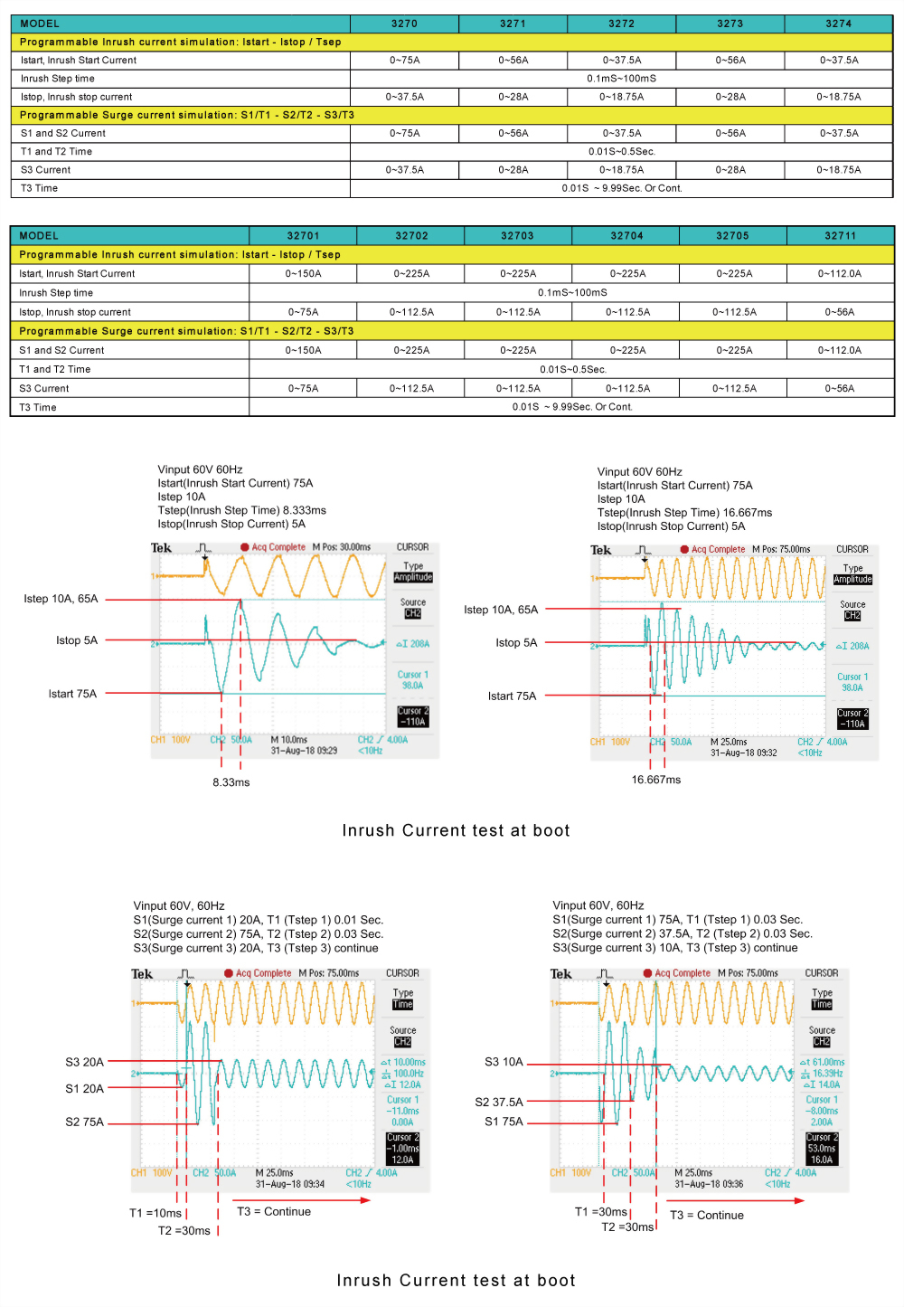
● Support the Inrush Current of the inverter at startup and Power Plug-in test when the power supply is turned on to verify the Inrush Current and the sudden connection of the appliance when the power is turned on (Surge Current), to verify if whether the Inverter output voltage transient response is stable, as shown in the figure below.
AC rectified load simulation meet the IEC62040-3 and IEC61683 test specifications
(IEC62040-3 UPS Efficiency Measurement non-Linear and IEC61683 Resistive Plus Non-Linear)
3270 AC & DC electronic load AC rectified load mode is fully compliance with the IEC test specification requirements for the UPS, IEC 62040-3 UPS Efficiency Measurement Non-Linear and IEC 61683 Resistive Plus Non-Linear, respectively, 3270 AC rectifier load mode uses CC + CR load mode and maintain current THD at 80%, to simulate the actual PV Inverter connected to the electronic device.
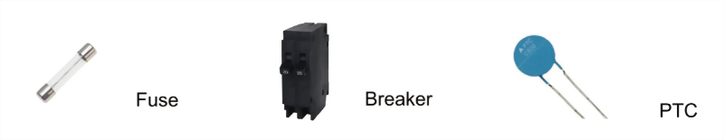
Current protection component includes Fuse, Circuit breakers and a new PTC Resettable fuse etc.., its function is when the circuit current exceeds the design of the rated value, that is, if the load exceeds the design of the current capacity, the circuit will be disconnected, in order to avoid overheating, even fire. Fuse is a one-time use of the protection components, Breaker and PTC can be reused.
The current protection components of the protection current value and the protection reaction time has usually a product of the relationship that is, the greater the current through the current protection component, the shorter the reaction time to protect the circuit. This is similar to energy protection components.
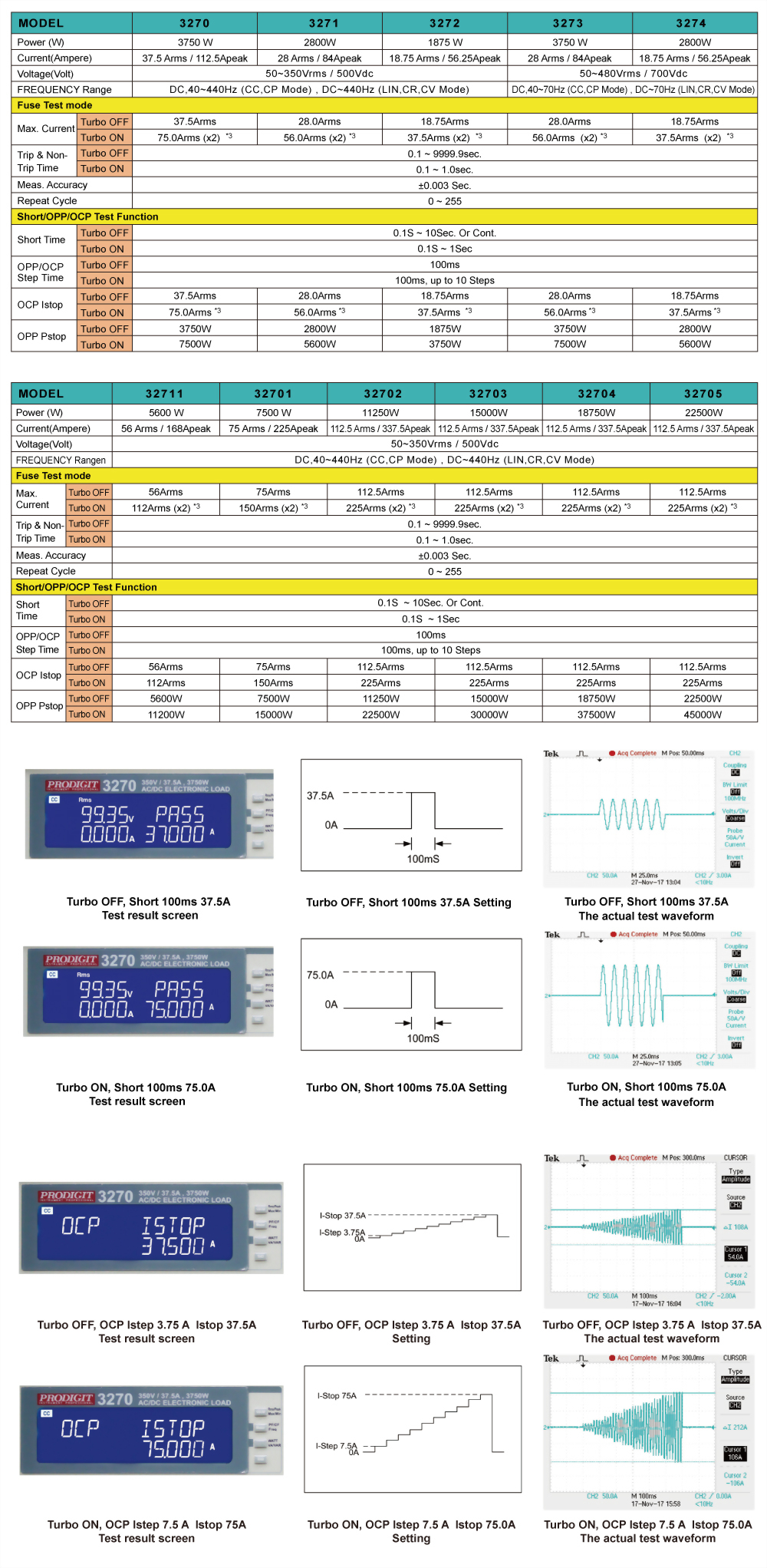
Due to this feature, the 3270 series AC & DC electronic load, in particular for the verification of current protection components, has developed a Fuse Test function to test and verify such protection element with an electronic load of rated current and power. When Turbo mode is set to ON, the test current can be up to double the maximum current within 1 second of test period. Take 3270 as an example, the maximum test current can be doubled to 75A. That is, when the Turbo mode of the 3270 series is ON, the test current value can reach to 2 units 3270 series ( normal mode ) within 1 second test period.
Basically, Fuse test has Trip (Blown) and Non-Trip (no Blown) 2 types.
In the Trip fuse test, it is used to test when there is too large abnormal current the Fuse or Bleaker must be able to provide the protection of the circuit break, that means current protection components need the fuse action, therefore the test current needs to be larger than the fuse current rating.
When the 3270 Series AC & DC electronic load detects a voltage lower than 1.0V, the LCD displays the number of Repeat Cycle and Current Protection Fusing Time XXXX.X sec.
In the Non-Trip (no Blown) test, the current protection component is required to achieve non-blow action, so the test current needs to be lower than the fuse current rating that is used to verify the fuse must not blow during normal current range. When the 3270 series AC & DC electronic load is not blown after the test time (Pulse Time) and the repeated Repeat number, the LCD displays the information of the Repeat number.
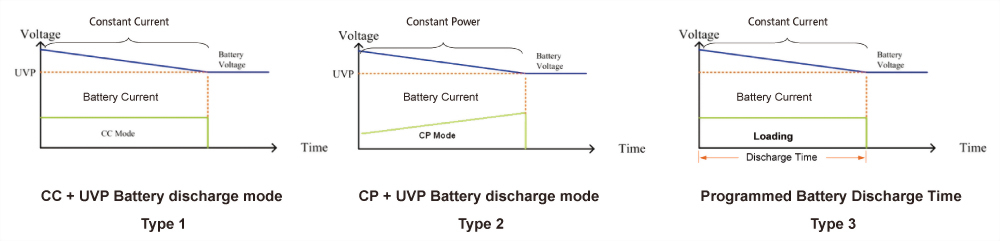
3270 series AC & DC electronic load has built-in new TYPE1 ~ TYPE3 battery discharge test, you can select the desired battery test mode, the test results can be directly displayed on the LCD display for battery AH capacity, the voltage value after discharge and the cumulative discharge time.
Parallel and three-phase control
The 3270 Series AC & DC load provides multiple units in parallel, three-phase applications that allows users to test applications with greater power or three-phase AC power, this is more flexibility to use the 3270 Series AC & DC Electronic Load for control. In parallel / three-phase operation, the user operates the unit as the operation of a single machine, as long as the Master can be operated, Slave1 and Slave2 will automatically sink the load and measurement. Parallel and three-phase connection as shown below.
Panel instructions
3271 AC & DC Electronic Load(350V, 28A, 2800W) 3271 Voltage Option : Voltage can be increased to 425V
3272 AC & DC Electronic Load(350V, 18.75A, 1875W) 3272 Voltage Option : Voltage can be increased to 425V
3273 AC & DC Electronic Load(480V, 28A, 3750W) 3274 AC & DC Electronic Load(480V, 18.75A, 2800W)
32711 AC & DC Electronic Load 350V, 56A, 5600W 32711 Voltage Option : Voltage can be increased to 425V
32701 AC & DC Electronic Load(350V, 75A, 7500W) 32701 Voltage Option : Voltage can be increased to 425V
32702 AC & DC Electronic Load(350V, 112.5A, 11250W) 32702 Voltage Option : Voltage can be increased to 425V
32703 AC & DC Electronic Load 350V, 112.5A, 15000W 32703 Voltage Option : Voltage can be increased to 425V
32704 AC & DC Electronic Load 350V, 112.5A, 18750W 32704 Voltage Option : Voltage can be increased to 425V
32705 AC & DC Electronic Load 350V, 112.5A, 22500W 32705 Voltage Option : Voltage can be increased to 425V
GPIB Card RS-232 Card
USB Card LAN Card Ordering optional function : External programming input *Need to purchase when placing an order, cannot be purchased after shipment*


